说明
Polymers. They’ve put a lot of bulky metal, glass, and stone out of work since they came on the scene in a big way back in the 1950s. These materials have definitely become more complex since that first Tupperware™ container emerged from an injection mold. They’re stronger, sleeker and more versatile than they’ve ever been because polymer science has evolved along with manufacturing technologies. Add conductive carbon black or graphite to a basic polymer and it will conduct electricity.
Add aramid fiber and the material can be bullet proof. Mix in silica and it will absorb infrared light. The possibilities are endless— and so are the options for reinforcing and filling. For every polymer form and function, there is a mineral, fiber, metal or carbon filler that will maximize its performance.

Mineral Fillers Overview
You’ve no doubt heard of talc filled polypropylene, but did you know that calcium carbonate is the number one mineral filler for plastics? There are quite a few options in the mineral family, and they not only reduce cost, they can also boost strength when added to a polymer. The shape of the mineral particle can be long and needle-like, spherical, flat and flaky, or broad. It’s one of these shapes that influences what kind of enhancement the particle can bring.
Added in at volumes ranging from less than 1 percent to more than 70 percent by weight, minerals are typically mined from the earth and then refined to produce uniform particle size distribution. Sometimes, additives such as lubricants and coupling agents are added to mineral fillers to improve dispersion in the compound and strengthen the bond between the mineral and the polymer.
While there are many mineral types used in plastic compounds, we’ve chosen to describe some of the most common in this article.
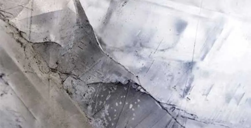
Calcium Carbonate
Chemical formula: CaCO3
Density: 2.71 g/cm3
Hardness (Mohs): 3
If you’re looking for a workhorse mineral filler, calcium carbonate will be happy to do the job. It’s a relatively inexpensive material, one that's widely used at large percentages to reduce the cost of a compound. Mined from marble or limestone, it’s often milled to create ground calcium carbonate (GCC).
Limestone is composed mostly of the mineral calcite (CaCO3) but may contain dolomite or another crystalline form of calcium carbonate called aragonite.1
Precipitated, or synthetic, calcium carbonate (PCC) is produced chemically from calcium oxide. PCC has fewer impurities than GCC and can be produced in specific particle shapes, narrow particle size distributions, and fine particle sizes.2
PCC and GCC are used as fillers in polymers such as polyethylene, polypropylene and polyvinyl chloride. They help make plastic parts opaque, but they don’t interfere with polymer colorants. PCC improves stiffness and impact in polypropylene and adds impact strength to rigid polyvinyl chloride for such applications as window profiles and siding. GCC may be surface treated to improve properties in the filled polymer.
1http://www.mineralstech.com/Pages/SMI/Ground-Calcium-Carbonate-(GCC).aspx 2http://www.mineralstech.com/Pages/SMI/Precipitated-Calcium-Carbonate-(PCC).aspx
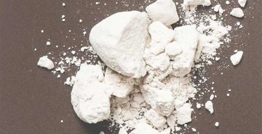
Kaolin
Chemical formula: Al2O3-2SiO2-2H2O
Density: 2.6 g/cm3
Hardness (Mohs): 2.5
Aspect ratio: 20:1
Kaolin, or white clay, is an aluminum silicate used in materials such as ceramics, paint, rubbers and plastics. Kaolin bumps up a material’s physical properties, including its tensile strength (ability to stretch without breaking) and its resistance to warping and chemical degradation. It also enhances brightness and can make plastics whiter and brighter with less titanium dioxide.1
Calcined kaolin is treated to improve its visual appearance and electrical properties. Surface-treated kaolins also have improved physical properties.
1BASF, “Kaolin” http://kaolin.basf.com/applications/ market/selected/plasticsandrubber
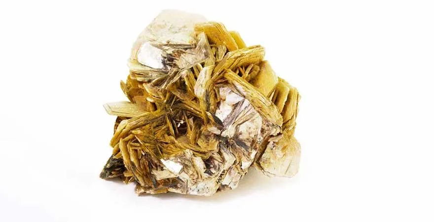
Mica
Chemical formula: KAl₂(Si₃Al)O₁₀(OH,F)₂
Density: 2.6 g/cm3
Hardness (Mohs): 2.5
Aspect ratio: 20:1
Mica is a platy (small, flat and flaky crystal) mineral that improves heat-deflection temperature, stiffness, and dimensional stability (tendency to retain original proportions). It also can dampen sound and vibration.1
These enhancements come from the high aspect ratio of the mica platelets (in other words, a large area of the platelet per thickness). Two types of mica are mined: the more common muscovite mica (a hydrated silica of potassium and aluminum) and phlogopite mica (a hydrated silica of potassium and magnesium).2
1Imerys Performance Minerals, Mica http://www.imerys-perfmins.com/mica/usa/mica.htm
2LKAB Minerals, MicaFort http://lkabminerals.com/Products/MicaFort
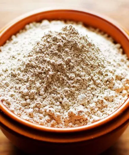
Silica
Chemical formula: SiO2
Density: 2.65 g/cm3
Hardness (Mohs): 7
There are various types of natural silica, including diatomaceous earth (diatomite), which is used as an antiblocking agent. Synthetic silica, which is manufactured into spherical particles, is used to improve dimensional stability and electrical properties.1
Fumed synthetic silica is used for reinforcement and for infrared-light absorption in greenhouse films.2
1 “Fillers and Reinforcements” in Plastics Additives, R. Gachter and H. Muller, Eds. (Hanser Publishers, 3rd ed. 1990).
2http://www.aerosil.com/product/aerosil/en/industries/plastics-thermoplastics/pages/default.aspx
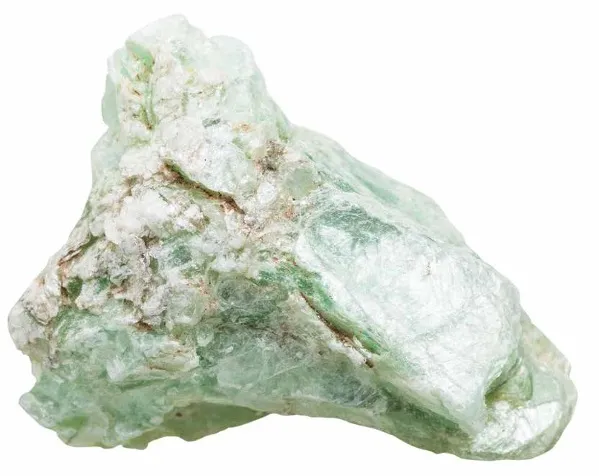
Talc
Chemical formula: Mg₃Si₄O₁₀(OH)₂
Density: 2.75 g/cm³
Hardness (Mohs): 1
Aspect Ratio: <10:1
Talc is a platy mineral widely used in polypropylene, polyethylene and polyamide to improve stiffness and other properties. Talcs with a high aspect ratio improve stiffness, heat resistance and dimensional stability. Talcs with fine particle sizes improve impact resistance.1
Surface treatments can improve dispersion and interfacial adhesion, or tack, which enhances the physical properties of a part. Talc can, however, make scratches more visible in a highly filled compound; submicron talcs, surface-treated talcs, and anti-scratch additives can mitigate this effect.
1Imerys Talc,
http://www.imerystalc.com/content/bu/Plastics/Functions/Dimensional_stability/america.php
加工
Some mineral fillers may be light and fluffy because of low bulk density, requiring special equipment and processing techniques to be added to and dispersed evenly in the polymer. Once encapsulated in the plastic, however, the compound pellets can easily be fed into an extruder or molding machine. A filled compound can differ from an unfilled polymer in the way it melts and flows in an extruder or injection molding machine— but it has better heat transfer and may require less energy for melting and cooling. Keep in mind, though, that increased heat transfer can make the process more sensitive and may require changes in tooling or process conditions.1
1J. Frankland, “How Fillers Impact Extrusion Processing,” Plastics Technology (Nov. 2011), www.ptonline.com/columns/how-fillers-impact-extrusion-processing

Abrasive Wear
Some highly filled mineral compounds can cause abrasive wear in injection molds or extruders, depending on the filler, the filler’s loading, and the processing conditions and metals used to make the tooling. Some minerals are harder and more abrasive than others.
On the Mohs scale of mineral hardness, which is used to indicate the scratch-resistance of minerals, talc is the softest mineral (with a hardness of 1) and diamond is the hardest (with a hardness of 10).
The table to the right lists the Mohs hardness of some minerals and materials used in processing equipment. Material and equipment suppliers can provide guidance on appropriate tooling and processing conditions.
Filler Combinations
Certain combinations of mineral fillers can improve properties for a specific formula and application. Mineral fillers can be combined with glass fibers, for example, to improve property balance.
Mineral fillers also improve the dimensional stability of plastic parts. Molded parts can shrink after they come out of the mold as the polymer cools. If the part shrinks more in one direction than another (anisotropic shrinkage), it can warp. Minerals with aspect ratios below 10:1 (such as talc) can help create more isotropic shrinkage, which is more uniform in all directions1, and improves dimensional stability. Higher aspect ratio minerals do more to improve tensile strength but have anisotropic properties because they orient with the melt during mold filling.1
In addition, a plastic part may soften, bend, or expand under certain conditions, particularly under a load at an elevated temperature. Mineral and fiber fillers can change the extent of expansion of a plastic, depending on loading levels and application requirements.
1http://machinedesign.com/materials/mineral-fillers-improve-plastics
概览
Plastics do not readily conduct electricity, or heat and cool the way metals do. Special fillers, however, can make a plastic compound electrically or thermally conductive.
A wide range of fillers—from conductive carbon black to carbon nanotubes—provide different levels of electrical conductivity. Conductive plastics prevent static electricity buildup in packaging, automotive fuel systems, and conveyor belts, to name a few. They also act as semi-conductors in cables and protect electronics from interference.
Some fillers make plastics electrically and thermally conductive, and others add thermal conductivity without electrical conductivity. Both types are needed for thermal management, as polymers become an increasingly common replacement for metal and can improve a product’s design, reduce its weight, and lower its cost.
(such as conductive carbon black, graphite, graphene, and carbon nanotubes) and some are thermally and electrically conductive. Graphite, which can be loaded at high concentrations in the polymer, can provide high conductivity but is highly anisotropic1, meaning its conductivity changes depending on direction. Both thermal and electrical conductivity are affected by the grade of graphite and by molding conditions for the polymer.1
(such as alumina silicate minerals, aluminum oxide, nitride and boron nitride) are thermally conductive but electrically nonconductive. Several of these are white and can be used with a range of colorants. for example, is called “white graphite” because it has a hexagonal, platy structure like graphite. The filler is also nonabrasive and has a low density.2 Aluminum oxide and nitride are more abrasive.
1 D. Bonacchi, “The carbon approach to thermal conductivity,” Compounding World (Feb. 2016).
2 3M™ Boron Nitride Cooling Fillers, http://multimedia.3m.com/mws/media/1045756O/3m-boron-nitride-cooling-fillers-brochure.pdf
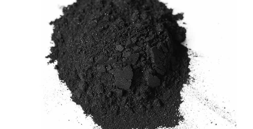
Conductive carbon black is a filler commonly used to create electrical conductivity. The fine black powder is added at relatively high levels and creates only black-colored parts. Some types of carbon black may slough, or shed, invisible dust. For most applications, this is not a problem; but this dust can destroy electronic circuits, making nonsloughing fillers preferable for electronics production and packaging.
Conductive Filler Types
Graphite fillers, which can be natural flake or synthetic, provide electrical and thermal conductivity. They also are thermally stable, chemically inert, and nonabrasive, and they provide low friction.1 This combination of properties makes graphite useful in gears, bearings and seals. Graphite fillers can be combined in formulas with other fillers, such as mica, talc, or fibers.1 Graphite can also be used with the fluoropolymer PTFE when chemical inertness and lubricity are important.
Metallic fibers that create electrical conductivity include copper, silver and stainless steel. They can withstand high temperatures and are resistant to most chemicals, abrasion and dirt2 and can be used with a range of colorants.
Imerys, “Specialty Carbons for Polymer Compounds” http://www.imerys-graphite-and-carbon.com/wordpress/wp-app/uploads/2014/04/Polymer_compounds1.pdf
2http://cameo.mfa.org/wiki/Metallic_fiber
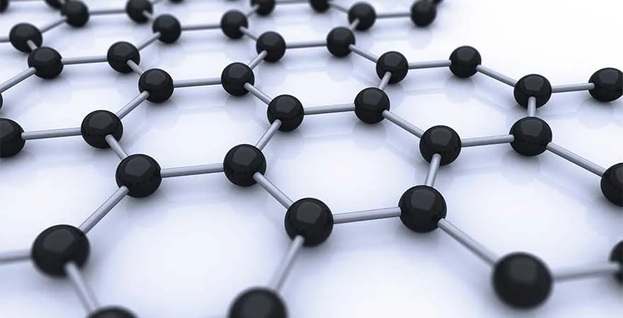
Graphene is a flat, single layer of carbon atoms in sheet form that is significantly stronger than steel.3 It has a high surface area-to-volume ratio, high tensile strength (how much it can stretch before it breaks), and high electron mobility (the speed at which its electrons move when voltage is applied).4 Graphene is not a new material, but it recently became commercially available and is now being used as a polymer additive.

Carbon nanotubes are carbon atoms linked in a cylindrical shape with diameters as small as 1 nanometer and lengths up to several centimeters.5 They have the highest strength-to-weight ratio of any known material. Because they have such a large surface area and high conductivity, these fillers can be added at low levels, where they do not interfere with colorability or mechanical properties.
3https://en.wikipedia.org/wiki/Graphene
4E. Boyson, et al., “Graphene: Sheets of Carbon-based Nanoparticles,” http://www.dummies.com/education/science/nanotechnology/graphene-sheets-of-carbon-based-nanoparticles/
5E. Boyson, et al., “Nanotubes: A Carbon-based Nanoparticle” http://www.dummies.com/education/science/nanotechnology/nanotubes-a-carbon-based-nanoparticle/
Electrical
The surface resistivity of a material determines the level to which it will conduct an electric charge. The lower the resistivity, the more conductive the material. Antistatic additives and electrostatic dissipative (ESD) fillers create low surface resistivity, preventing the buildup and uncontrolled discharge of static electricity.
For example, ESD protection is important in the production and packaging of electronic components. Compounds at the high end of the resistivity scale shield against electromagnetic interference (EMI) or radio-frequency interference (RFI).1 Faster data transmission and broader electromagnetic frequencies are driving the need for better EMI/RFI protection for electronic devices.2
EMI/RFI shielding fillers include conductive stainless steel fibers, carbon fibers, nickel-coated carbon fibers, metal flakes, graphite flakes, carbon nanotubes, carbon nanofibers and graphene.
To make a plastic compound electrically conductive, there must be enough conductive filler particles—and they must be dispersed well enough throughout the polymer—to form a network through which an electrical current can flow. The point where conductivity begins is called the “percolation threshold.”The loading of filler needed to reach this threshold varies by the type and grade of conductive filler and the amount present per volume of polymer.
1https://www.avient.com/products/engineered-polymer-formulations/conductive-signal-radiation-shielding-formulations/stat-tech-static-dissipative-electrically-conductive-formulations
2B. Fairchild, T. Hughes, S. Stephan, and Avient Corporation, “EMI/RFI Shielding Formulations for Use in Advanced Electronic Systems” (2014).
Thermal
While conventional plastics retain heat, plastics containing thermally conductive fillers distribute heat and carry it away from the heat source. The thermal conductivity of conductive plastics is not as high as that of metal, but conductive plastics can be just as effective as metals in thermal management, transferring heat by conduction (which depends on the material) and convection (which depends on the design of the system and the flow of air or liquid around the polymer part).
Thermally conductive plastic parts may be anisotropic—meaning they conduct heat better in one direction (in the plane of the conductive filler, either axial or transverse) than in the perpendicular directions (through the plane of the filler). The design of the part, the characteristics of the filler (e.g. particle size and aspect ratio), and molding conditions can affect the balance of in-plane and through-plane conductivity.
Thermally conductive plastics are replacing aluminum in such products as the heat sinks used to reduce hot spots in LED lighting because they are more lightweight and provide comparable thermal management.
加工
It is important to properly disperse thermally or electrically conductive filler in the polymer compound. When molding an electrically conductive compound, create a silver or fibrous surface, not a resin-rich surface, and use a low extruder barrel temperature.1 For electrically nonconductive but thermally conductive compounds, raise the barrel temperature.2
Other keys to molding electrically conductive compounds are slow injection speeds and low back pressure (e.g., 50 psi).1 Use 50 percent to 75 percent of the injection pressure for the pack and hold pressure.
The best gates, or openings, for molten plastic to enter the mold are hot runner molds, full-round runners, or modified trapezoid runners. Half-round runners are not recommended. Proper venting is also important—place vents at the end of the fill and anywhere potential knit or weld lines could occur. All vents should allow trapped air and gasses to escape to the area outside the mold.
Regardless of these suggestions, you need to experiment with your equipment and the polymer to be compounded in order to establish the processing you want.
1https://www.avient.com/sites/default/files/2020-09/stat-tech-tri-fold-processing-guide.pdf
2https://www.avient.com/sites/default/files/2020-12/therma-tech-processing-guide.pdf
概览
Fibers made from glass, carbon, aramid and other materials can be chopped and added to thermoplastic compounds to produce fiber-reinforced plastic (FRP) that can be injection molded or heat formed. Chopped fibers improve stiffness and other properties so that FRP can replace higher-performing materials and even metals. The following sections describe various fibers and their benefits.
Glass
Glass fibers are commonly added to nylon, polypropylene and other polymers to make glass-fiber reinforced plastic (GFRP) that is stiffer and stronger than unfilled polymer. Short-glass fiber (SGF), which is chopped into lengths of less than one-half inch, improves stiffness and impact strength and reduces shrink.
Long-glass fiber (LGF), which can be longer than one-half inch, can be tougher and more impact resistant (especially in cold temperatures) and have more tensile strength (ability to stretch without breaking) than a comparable SGF composite.
Long fibers are more dimensionally stable (tendency to retain their original proportions), are less prone to permanent damage from stress (creep and fatigue), and have better surface appearance than short fibers.
A GFRP usually is between 10 percent to 50 percent glass fiber by weight. Typically, the more fiber the greater the improvement, as long as the fibers are blended well and the polymer adheres to the fibers. If adhesion is poor, the composite can fail. Fiber adhesion can be improved by treating or coating the fibers and by adding coupling agents to the formula.
Because an LGF’s advantage comes from its longer length, it is important to avoid breaking the fiber during processing. LGF-reinforced plastic can be molded in standard equipment, but manufacturers should follow recommended processing guidelines, such as those described in the of this e-book.
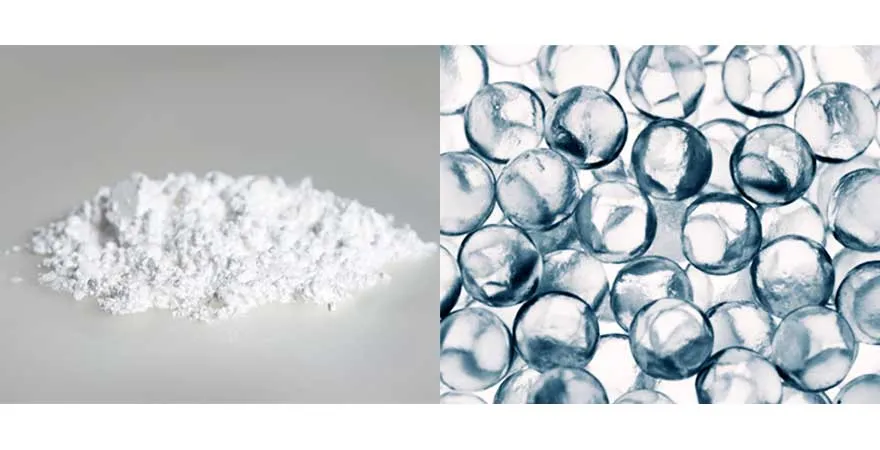
Milled Glass + Glass Beads
Unlike chopped glass fibers, is a fine powder used to thicken resin. Some milled glass is made from manufacturing byproducts, which makes it eco-friendlier.
Used in plastics are solid or hollow spheres or microspheres, which may be coated with coupling agents to improve bonding between the glass and the polymer. Glass beads are sometimes produced from recycled glass using a chemical process that creates precise spheres, which can be dispersed evenly and packed closely to allow high filler loading.
In polymer compounds, solid glass beads improve mold flow and surface appearance. They also improve dimensional stability, the ability to resist losing shape under a load, abrasion resistance and surface hardness. Solid glass beads— which range from 20 to 40 micrometers in diameter—can be used as a partial replacement for glass fibers to reduce cost, shrinkage and warpage because their spherical shape makes them more uniform in all directions.1,2 Hollow microspheres reduce part density, improve flow and dimensional stability, and provide sound and thermal insulation.3 These additives can be used as an alternative to mineral fillers.
1http://pottersbeads.com/egm/NorthAmerica/Products/SolidGlassMicrospheres/SPHERIGLASS.aspx
2http://polymer-additives.specialchem.com/centers/solid-glass-beads/properties 3http://pottersbeads.com/egm/NorthAmerica/Products/HollowInorganicMicrospheres.aspx
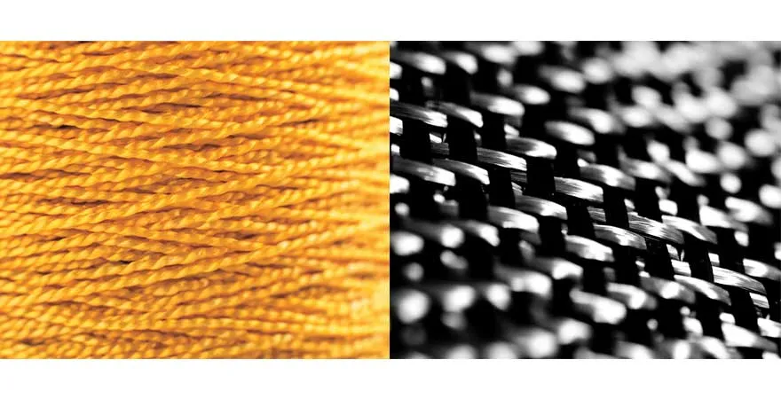
Fiber Reinforcements: Carbon + Aramid
Long- and short- can be used in thermoplastic compounds for lightweight, high-end reinforcement. Carbon fibers are stiffer, have more tensile strength, and are more creep resistant than short-glass fibers. Although carbon fibers are more expensive than glass fibers, new technologies are making carbon fibers more affordable1. Short-carbon fibers also can be used to improve electrical conductivity.
Most well known as the brand Kevlar™, is produced by spinning a liquid chemical blend into a solid fiber. Aramid is heat- and wear-resistant, and it’s lighter but stronger than carbon fiber.
These qualities make it ideal for protective clothing and helmets, sporting goods, cables and as an asbestos replacement. Unlike carbon fiber, aramid fiber does not conduct electricity.
P. Mapleston, “The future could be carbon,” Compounding World (Oct. 2016). www.compoundingworld.com

Biobased Fibers + Fillers
Biobased fibers and fillers come from renewable resources, such as the waste from harvesting and processing agricultural products or sometimes from nonfood crops, such as hemp, grown specifically for industrial use.
These materials typically have a more favorable life cycle analysis (LCA)—the product’s lifetime effect on the environment—and a smaller carbon footprint than traditional, non-biobased fibers and fillers.
In many cases, biobased fillers and fibers also have a lower density, which can help when trying to reduce weight. Natural fibers also have lower abrasion than glass fibers, resulting in less wear on manufacturing equipment. It can be challenging to source raw material for biobased fiber, and it is more sensitive to moisture and less resistant to heat than other fibers.1
1J. Markarian, “Renewable reinforcements hit the road,” Compounding World (March 2015) www.compoundingworld.com
Fiber Combinations
Combining fiber types, such as long-glass and long-carbon fibers, or combining fibers with minerals, such as talc, can optimize the cost and physical properties of your composite.
加工
Keep in mind that high levels of fillers and fibers can be abrasive to processing equipment. Minimize equipment wear by using hardened or abrasion-resistant materials and coatings for extruder barrels and screws and mold tools.
部件设计
Part design and molding conditions can be just as important as polymer formulation. Fibers—especially long fibers—undergo stress during the injection molding process. As they cool, any defects caused by this stress can lead to warpage, or loss of the intended shape. Proper positioning of the gate, or mold opening, and proper mold design can minimize flaws.
Molding with Long-Fiber Composites
To preserve the fiber size, use long-fiber compound pellets instead of standard pellets. Use an extruder feed throat that is 2 feet 6 inches long or longer to avoid bridging, and use general purpose metering screws (not mixing screws) with deep flights. In the mold, use general purpose nozzles (not tapered nozzles) and large, free-flow gates. Runners should be designed with a full round gate and no sharp corners.1
https://www.avient.com/products/engineered-polymer-formulations/high-temperature-polymer-formulations/compl-t-long-fiber-reinforced-structural-thermoplastics
Metallic Fillers Overview
Plastics have many advantages over metals—they are lighter and offer more design flexibility, among other benefits. Sometimes, however, a part needs properties only metal can offer, such as weight, high density, radiation shielding, or the ability to be identified by a metal detector.
Metal-filled polymers provide the best of both worlds, while offering thermal and electrical conductivity and ease of manufacturing because they can be injection-molded. Metallic fillers also are not as abrasive as glass fillers (which is good for injection molding equipment) and can make a plastic part that weighs up to 80 percent of the weight of its full-metal counterpart.
The following sections describe common metal fillers and their benefits.
Stainless Steel + Copper Fibers

Stainless steel fibers are an excellent replacement for aluminum. Stainless steel doesn’t oxidize like aluminum and doesn’t require texturing or polishing after cutting or die-casting, which ultimately shortens production time.

Copper filler, often in powder or flake form, is also a good substitute for aluminum, as it has a much higher melting point and doesn’t corrode like aluminum will.
Tungsten
Tungsten filler is used to protect equipment, operators and patients from radiation during an X-ray. The thickness and level of the tungsten filler determines whether the radiation shielding is directional or comprehensive.
Tungsten filler also can replace lead in projectile ammunition— satisfying lead level regulations—and provides weight and balance in such sporting equipment as golf clubs and weight training vests.
Iron Oxide
The iron oxides magnetite and hematite are used to add density to such plastics as polypropylene, polyamides (nylons) and polyethylene, giving them the weight of metal but the versatility of plastic.
These oxides have high thermal and electrical conductivity (although hematite can conduct more heat), can block radiation, and can dampen sound. Both materials also can be used to make plastics that are attracted to magnets. Hematite can be used as a pigment, adding a gray metallic sparkle to a compound.
加工
It is critical to disperse metallic filler effectively in a compound to avoid backup at the injection mold gate, or opening, which can experience wear when exposed to high levels of metallic filler. Experts recommend using inserts for large-volume production, and because a long dwell time in the barrel may cause degradation, use a minimum of 20 percent to 50 percent of barrel capacity per shot.1 Purging is also important. You should use high-density polyethylene or high impact polystyrene purge compounds at startup and shutdown and flush the barrel with a low melt-flow index polypropylene between production runs.1
To prepare your equipment for metal-filled compounds, start with glass-filled material in the same base resin—it’s less expensive. Then add metallic filled material once you have set up your process. Also, avoid allowing metallic filler to sit in the barrel at high temperatures for long periods of time—this could degrade the base resin. Because the thermal conductivity of metal-filled material is high, you want the material to set up higher and faster in your mold, so fill the mold more than you would with another compound.
1Gravi-Tech Processing Guide https://www.avient.com/sites/default/files/2020-10/2020-gravi-tech-processing-guide.pdf
